
What Is a Battery Management System (BMS)?
BATTERY BASICS
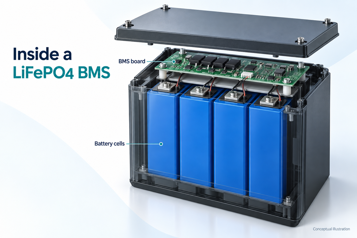
A battery management system (BMS) is an electronic system that monitors a rechargeable battery and manages its operation within defined limits. In a LiFePO4 battery, a BMS typically monitors cell voltage, current, and temperature. It can interrupt charging or discharging when a protection condition occurs. Depending on its design, it may also balance cells, estimate state of charge, and communicate battery information.
For an RV, solar, or backup power system, this matters because a battery's overall voltage does not reveal everything happening inside it. One cell can reach a limit before the others, or a temperature restriction can make charging inappropriate even when the battery still has usable energy.
This guide explains what a BMS measures, how its MOS switches work, and what six common protection functions mean in everyday use. For the chemistry behind the battery, start with What Is a LiFePO4 Battery?.
What Does a BMS Monitor?
The BMS receives measurements from sensing circuits connected to the battery. These measurements help it decide whether charging and discharging can continue.
| Measurement | What it tells the BMS | Why it matters |
|---|---|---|
| Cell voltage | Voltage of each monitored series cell or parallel cell group | Identifies a group approaching an upper or lower voltage limit |
| Pack current | Current flowing into or out of the battery | Supports charge/discharge current protection and, in some systems, charge tracking |
| Temperature | Temperature at fitted sensors, such as near cells or power switches | Helps enforce the temperature limits configured for the battery |
| Pack voltage | Overall battery voltage | Provides system-level information alongside individual cell measurements |
Sensor coverage matters. A sensor measures temperature at its location; it does not directly measure every point inside the battery. Likewise, cells connected directly in parallel share a monitored group voltage, so a typical BMS does not obtain a separate voltage reading for every physical cell in that group.

How Does a BMS Control Charging and Discharging?
The basic sequence is measurement, comparison, and control. The BMS checks readings against configured conditions, then controls the relevant charge or discharge path when necessary.
Charge and discharge MOSFETs
In many compact battery packs, the BMS uses power MOSFETs as electronic switches. MOSFET stands for metal-oxide-semiconductor field-effect transistor; battery descriptions sometimes shorten this to “MOS.”
Charge and discharge MOSFETs are commonly arranged so the circuit can restrict the relevant current direction. The exact behavior depends on the circuit and control logic. A charging restriction does not necessarily mean discharge is also disabled.
During normal operation, the switches conduct current. During a qualifying fault, the controller turns the appropriate switches off. This switching role differs from the charger's job of regulating the normal charging voltage and current.
Other systems use contactors or send control signals to external chargers and loads. A BMS does not have to be one internal circuit board to perform battery management.
Protection thresholds and recovery
A protection threshold is a condition that triggers a protective response. A design may also specify a detection delay, a separate recovery threshold, or conditions such as removing the load before reconnection.
For example, a battery that stops discharging because of low cell voltage may require an approved charging procedure before normal operation resumes. A temperature restriction may remain active until the measured temperature returns to the permitted range.
The exact thresholds, delays, and recovery rules are product-specific. They are not universal charging targets.
Why Does Each Cell Need Monitoring?
A series-connected battery's total voltage is the sum of its cell-group voltages. That total can conceal differences between groups.
Consider two hypothetical four-cell packs measured under the same conditions:
| Example | Cell 1 | Cell 2 | Cell 3 | Cell 4 | Total |
|---|---|---|---|---|---|
| Pack A | 3.40V | 3.40V | 3.40V | 3.40V | 13.60V |
| Pack B | 3.60V | 3.35V | 3.35V | 3.30V | 13.60V |
The totals match, but Pack B has a larger voltage spread. Its highest-voltage cell may reach the configured charging limit earlier than the others. During discharge, the lowest-voltage cell can determine when output must stop.
These numbers illustrate why individual monitoring matters. They are not recommended operating limits, measured BUKNUWO data, or a way to calculate each cell's exact state of charge. Cell voltage also changes with current, temperature, and rest time.
Six BMS Protection Functions Explained
The following table describes common protective responses. Actual coverage depends on the battery's hardware, firmware, sensors, and enabled settings.

| Protection | Condition being checked | Typical protective response |
|---|---|---|
| Overcharge | A monitored cell exceeds its upper voltage threshold | Interrupt charging |
| Over-discharge | A monitored cell falls below its lower voltage threshold | Interrupt discharging |
| Overcurrent | Charging or discharging current exceeds a configured limit for the specified duration | Interrupt the affected current path |
| Short circuit | A severe fault meets the short-circuit detection criteria | Rapidly interrupt discharge |
| High temperature | A monitored temperature exceeds its configured limit | Restrict charging, discharging, or both |
| Low temperature | A monitored temperature falls below an enabled operating limit | Restrict charging and, where implemented, discharging |
Temperature protection behavior should always be checked separately in the battery's specifications.
Overcharge protection
Overcharge protection responds to excessive cell voltage during charging. In a series pack, one cell reaching its limit can stop charging for the pack, even if the other cells have not reached that point.
Use the recommended charging profile for normal operation. Repeatedly reaching a BMS cutoff is not a substitute for correctly setting the charger.
Over-discharge protection
Over-discharge protection interrupts output when a monitored cell reaches its configured low-voltage condition. This helps limit further discharge through the controlled output path.
A cutoff does not mean the cells contain absolutely no energy, and it does not eliminate the battery's internal consumption or self-discharge. Follow the manufacturer's recovery and storage instructions instead of leaving a depleted battery unattended for a long period.
Overcurrent protection
An overload can occur when connected equipment draws more current than the battery is designed to supply. Excessive charging current can also require protection. Charge and discharge limits may differ.
The trip threshold is not necessarily the continuous current rating. A protection design may allow a brief surge but interrupt a longer overload. Evaluate the stated continuous limit and any peak-current duration separately.
Short-circuit protection
A short circuit can create a very high fault current. A BMS with suitable detection and switching circuitry can interrupt discharge when its short-circuit criteria are met.
This function does not replace properly sized wiring and external circuit protection. The battery, cables, fuse, connections, and connected equipment form one system; the BMS cannot make an unsuitable installation acceptable.
High-temperature protection
Temperature sensing may cover cells, MOSFETs, or both. A BMS can restrict operation when a monitored location becomes too hot, according to its configured limits.
Stopping current does not actively cool the battery. Continued exposure to heat can remain a problem after a cutoff, so installation conditions still matter.
Low-temperature protection
Low-temperature charging protection blocks charging when measured battery temperature is below the permitted charging limit. That limit must come from the specific battery's documentation.
Charging and discharging can have different temperature limits. Check both operating ranges in the specific battery's documentation rather than assuming they are the same.
Low-temperature protection and self-heating are separate features. A cutoff stops an operation; a heater adds heat. Having one does not establish that the battery has the other. A weather forecast also does not replace the temperature measured inside the battery.
How Does Cell Balancing Work?
Cell balancing manages differences in charge between cells or cell groups in a series string. Its purpose is to reduce the imbalance that can cause one group to reach a charging or discharging limit before the others.
Passive balancing
Passive balancing removes a small amount of charge from selected higher-charge cells through a dissipative path, typically a resistor. That energy becomes heat. It does not transfer that energy into a lower-charge cell.
The BMS may enable balancing only within certain voltage, temperature, or operating conditions. The balancing current and available balancing time affect how much imbalance it can correct.
Active balancing
Active balancing uses energy-transfer circuitry to move energy between cells or between cells and the pack, depending on the design. It adds circuit complexity, and the direction and timing of transfer vary by implementation.
Neither method repairs a damaged cell or reverses capacity loss from aging. Also, similar cell voltages at one moment do not prove identical cell capacity. The term “cell balancing” alone does not tell you which method a battery uses.

What Does a BMS Current Rating Mean?
Current and capacity answer different questions. A hypothetical 100Ah battery has a stated charge capacity; a 100A continuous discharge rating describes a current limit under specified conditions. The two numbers are not interchangeable.
The usable system limit also depends on the cells, terminals, internal connections, external cables, and other components. A BMS label by itself does not establish the complete battery's permitted output.
For an inverter load, an approximate battery-side current calculation is:
Battery current (A) ≈ AC load power (W) ÷ [battery voltage (V) × inverter efficiency]
For an illustrative 1,000W AC load, a 12.8V battery voltage, and an assumed 90% inverter efficiency:
1,000W ÷ (12.8V × 0.90) ≈ 86.8A
At 12.0V, using the same load and assumed efficiency:
1,000W ÷ (12.0V × 0.90) ≈ 92.6A
This shows why current can rise as battery voltage falls while an inverter supplies the same AC power. It is not approval to pair this load with a particular battery. Actual efficiency, startup surges, other connected loads, and the manufacturer's operating conditions still matter.
What a BMS Can and Cannot Tell You
Some BMS designs provide an app, display, or communication port. Others perform protection without exposing detailed readings to the user. Bluetooth, state-of-charge reporting, and fault history are additional capabilities to verify.
State of charge (SOC) is an estimate of remaining charge. A system may combine current tracking with voltage, temperature, and a battery model. LiFePO4's relatively flat voltage curve makes voltage alone an imprecise percentage indicator over much of its range.
A displayed percentage therefore does not override a cell-voltage or temperature protection condition. A battery showing remaining charge may still need to stop supplying a load if another operating limit is reached.
Common Misunderstandings About BMS Protection
- “A BMS makes any charger compatible.” Charger voltage, current, and charging behavior still need to match the battery's requirements.
- “All BMS-equipped batteries have the same protections.” Feature coverage and recovery behavior vary by model, especially for low-temperature protection and communications.
- “A higher BMS amp rating adds more stored energy.” Energy depends on battery voltage and capacity. Increasing an electronic current rating does not add cells or amp-hours.
- “Balancing means every cell is always identical.” Balancing operates within design limits and cannot remove every difference in capacity, resistance, or temperature.
- “An internal BMS approves any series or parallel connection.” Whole-battery interconnection must follow the battery manufacturer's permitted configurations.
Frequently Asked Questions
Is a BMS the same as a battery charger?
No. The charger provides the normal charging voltage and current profile. The BMS monitors the battery and can restrict charging when a protection condition occurs. Some systems coordinate the two through communication or control signals.
Does a 100A BMS mean the battery has 100Ah of capacity?
No. Amps describe current; amp-hours describe charge capacity. Also check whether the advertised amp rating refers to continuous discharge, continuous charging, or a short-duration peak.
Can a battery discharge while the BMS blocks charging?
Some designs allow this. For example, a charging restriction may leave discharge available if discharge conditions remain acceptable. The actual response depends on the circuit, fault type, and configured control logic.
Do all LiFePO4 BMS boards have low-temperature protection?
No. Confirm the feature for the exact battery model, including whether it applies to charging, discharging, or both. A temperature reading in an app does not by itself prove that automatic low-temperature cutoff is enabled.
Does the BMS balance separate batteries connected together?
An internal cell-balancing function normally manages the cells within its own battery. It does not automatically provide balancing between separate battery enclosures. Approved battery-bank configurations and any system-level management are separate considerations.
Does a BMS extend battery life?
A correctly implemented BMS helps the battery operate within defined limits and can reduce exposure to damaging conditions. It cannot promise a fixed lifespan. Temperature, depth of discharge, charging habits, storage, cell quality, and aging still affect service life.
Continue Learning
Return to What Is a LiFePO4 Battery? to connect BMS protection with battery chemistry, voltage, and capacity.
When comparing BUKNUWO models for an RV, solar, or backup system, read the exact battery specifications for continuous charge and discharge current, temperature protection, balancing features, and permitted series or parallel connections. Use those documented limits to evaluate the complete system.